3D Matchmoving
3D Environment in Nuke:
Nuke as a 3D environment that is similar to that of Maya and ZBrush. This allows for the creation and manipulation of 3D objects and cameras, this 3D environment can then be rendered in a 2D format and used in the 2D environment of Nuke.

The Nuke 3D environment.

Above is the node graph of a simple 3D scene. Nodes that are related to the 3D element of Nuke have round edges and are normally red in colour. At the top of the nodal tree you can see two 3D objects, a cube and a cylinder. These objects have an image connected to them, these images are applied as textures to the 3D objects (See top image). These objects are both connected to a 'Scene' node, this node allows for multiple 3D elements to be displayed together, in one scene. The scene node also has a 'Camera' node attached to it, this node creates a camera that can be manipulated and animated in the same way as camera in other 3D softwares. Next in the nodal tree is a 'Scanline Render' node, this node is receiving both the Scene and camera nodes as inputs. The node takes these inputs and renders the scene, through the view of the camera and produces a 2D image that can be viewed in the 2D viewer.
3D Camera Projection:
3D camera projection is a technique that allows for 2D images to be projected onto 3D geometry, this can be used to create realistic 3D effects using basic 3D objects and 2D artwork or photography. For example, the clip below uses camera projection to create an illusion of moving through a tunnel. This is achieved using a still photograph and a basic 3D cylinder object.
Two methods can be used to create a script for this effect. The nodal trees below show these methods.

Method 1 uses two separate cameras, one that is input into the 'Project3D' node, and one into the 'Scanline Render' node. The first camera is used to project the image onto the 3D geometry and the second camera is used to render the outcome, the second camera is animated. In method 2 one camera is used, this camera is also animated, however using an animated camera for projection wouldn't work, so a 'FrameHold' node is used. This freezes the on the first frame of the animated camera, this effectively makes the camera static allowing it to be used for projection. Below is an example of method 2 in 3D space.

This technique can be used to create more complicated scenes using more geometry, for example, the clip below is made up of five pieces of geometry.


The images above show the 3D environment and node graph of the prison cell clip. The script used multiple instances of the same image to create the cell. Parts of the image are cutout using roto shapes and the 'Premult' node, these image parts are then projected onto 'planes' or 'cards', which are positioned in 3D space to form the shape of the cell in 3D. Merge nodes are used to combine the outputs of the various 'ScanlineRender' nodes, two 'defocus' nodes are used to create a change in focus as the camera moves through the bars of the cell.
3D Tracking and Cleanup in Nuke:
Nuke has the ability to 3D track video. This means that I can gather data from a 2D image sequence and produce a 3D point cloud from that data. This allows for 3D geometry to be tracked into a shot, this can be combined with camera projection to create cleanup patches. As seen below.

The image above shows the node graph of this technique. The first step is to remove any lens distortion from the image sequence, this is done by using an ST map, a 'reformat' node is used, this overscans the image so that any increase in size caused by the un-distortion isn't lost. The next step is to create a cleanup patch, this is done in the same way as creating a normal 2D patch. Using a the 'rotopaint' node with a 'framehold' node and a 'premult'. The shot then needs to be tracked, a 'CameraTracker' node is used. This node uses points throughout the sequence to calculate a 3D camera that matches the movement of the real camera. As this shot has a lot of water the tracker node needs to be told not to use the water when tracking, otherwise the movement of the water would throw the track off. This can be done be creating a roto shape that excludes the water and any other moving parts of the shot, using a copy node to acquire the alpha channel data the camera tracker node has to have the Mask setting set to Source Alpha. The tracker can then be used, once tracked, the data has to then be solved, this creates a 3D camera. The camera can then be used with a project3D node, this has to have a framehold that matches the framehold set for the cleanup patch. The patch can then be projected onto a card using the solved camera. The cleanup patch then needs to be re-distorted so that it matches the original sequence. The patch can then finally be applied to the shot using a merge node.
Tracking in 3DEqualzier:
3DEqualizer (3DE) is a program dedicated to 3D tracking, it makes the process of 3D tracking more manual, this results in more precise 3D tracks once the camera is solved.

In 3DE the footage is imported under the 'Cameras' tab. When browsing for the footage 3DE displays a file tree, once you have navigated to your footage, you can click 'Show Image' to double check that you've found the correct footage.

Once the footage is imported, you have to create a 'Buffer Compression File' this is a way of 3DE creating a cache file so that the footage can play back smoothly. This is accessed through, Playback > Export Buffer Compression File.

Once the file has been cached several attributes have to be changed. The filmback height and width have to be changed to match the sensor in the camera used, the focal length also has to be changed to match the lens used. These attributes are accessed by double clicking on the 'Default lens'.


The footage is now ready to track. To begin tracking you first have to create a tracking point, this is done by holding left ctrl and left clicking. When a point is created two bounding boxes are also created, the inner of these boxes defines the pattern that 3DE will track and the outer box defines the area that 3DE will search to find this pattern. The points can be seen under the scene dropdown > Point Groups, pgroup#1.
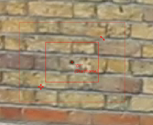

To track this point you first have to gauge the point, this can be done by pressing 'G', once the point has been gauged it can then be tracked, this is done by pressing 'T'. 3DE will then attempt to track the point. In this example the selected point goes off screen, to tell 3DE that the point can no longer be tracked you set the final frame that the point is visble as the end point. This is done by pressing 'E'.

To calculate a good solve 3DE needs at least 10 points that span the whole sequence, the example below has 25 points. Solving the track is done through 'Calc > Calc all From Scratch' or by pressing 'Alt+c'.


Once calculated the data can then be viewed in 3D, this is accessed by changing the viewing mode to '3D Orientation'. The data can also be viewed in the 'Lineup Controls' viewing mode, this shows how well the solve matches up to the 2D tracking data.


To further improve the quality of the track some attributes need to be changed. The focal length won't be exactly 35mm due to a variety of real world factors, 3DE can work out a close estimate of the true focal length. To do this you have to set the focal to 'Adjust' in the lens attributes, then use the 'Parameter adjustment' window to compute the true value. This process is repeated for the Distortion and the Quartic distortion. Once completed you have to transfer the parameters to the track, the track then has to be solved again.


To see the improvement you can use the 'Deviation Browser', this shows how well individual points have tracked. The deviation browser shows a value, the aim is to get a value between 0 - 1.

Once you are happy with the track and solve, you need to bake the scene. This is done through Edit > Bake Scene v1.2, in the 3D orientation viewing mode. Once baked you can then export data from 3DE into various different softwares. In this example the data is being exported into Nuke. To export the camera you go through 3DE4 > Export Project > Nuke... v1.6, this creates a .nk file which can be opened in Nuke. Locators can then be exported, this is done through Geo > Export OBJ, this creates a .obj file than can be opened in Nuke and other 3D software. Finally when working with Nuke the lens distortion data needs to be exported, this is done through 3DE4 > File > Export > Nuke LD_3DE4 Lens Distortion Node.


This exported data can be used in Nuke. When imported the camera script opens as shown below, the data is organised using backdrop nodes, these nodes can be duplicated and place where needed in the rest of the script.

Below is an example of a node graph of how to setup a basic test of the track (also below). As the locators and the cylinder are imported as 3D objects they can have textures applied in the same way as the 3D nodes built into Nuke. An overscan node is used as the tracking data utilised undistorted data there will be data lost if the default format is used. The reformat node used of the overscan has to have the resize type set to none. After the ScanlineRender node the shot has to be redistorted so that it matches the original sequence. This is done by using the lens distortion exported from 3DE and setting the direction to Distort. This pipeline can then be merged over the original footage.

The nodal tree and video below show a basic cleanup patch utilising the 3D tracking data. The process is the same as using the built-in camera tracker node, but using the 3DE camera data in its place. The sequence first has to be undistorted. A BlackOutside node is used first in the chain, this removes any data that gets stretched by the overscan node. The lens distortion data exported from 3DE is next in the chain, this is set to undistort, the overscan node following it ensures that no data is lost from the undistortion. Next a patch is created, this is done in the same way as any other patch is created, wether that is 2D or to be used in 3D space. The patch is then projected onto a card using the 3DE camera data. The card can be correctly positioned in 3D space using the locators exported from 3DE. The final process is to redistort the patch so that it lines up correctly with the original plate. This done by using an overscan and a lens distortion node, but with the lens distortion node set to distort. The patch can then be merged over the original plate using a merge node. In this example it is a very basic cleanup of the sign.

Assignment 01:
Final Render:
The video above shows the final comp of the first assignment. The breakdown video below shows the various elements of the composition. For this assignment the task was to 3D track the scene using at least 40 tracking points, then using the tracking data, remove a fire escape sign from the shot. A 3D object was also added to show the stability of the track.
Breakdown:
The video below shows a sped up screen recording of the 3D tracking process. This involved placing and tracking around 45 points, solving a camera from these tracked points and then increasing the accuracy of the track using focal length and lens distortion adjustments.
Tracking Process:
The image below shows the nodal tree of the Nuke script. I used several backdrop nodes to separate the different parts of the script, this allows the script to be easily understood by others and also makes problem solving easier.
Nuke Script:

Nuke Script Breakdown:

The first step in creating the Nuke script was to import the data from the 3DE track. The camera data is exported from 3DE as a .nk file, this can be opened by dragging and dropping the file into the nodal workspace. The lens distortion and geo nodes are also opened in this way. I decided to keep the original copies of the data separate so that they were easy to access when creating the rest of the script.

The next four images show how the cleanup patch was composited. The first step was to remove the distortion from the original plate, this is done by using the lens distortion node exported from 3DE. As the un-distorted image will be larger than the original image a reformat node has to be used so that no data is lost, the "BlackOutside" node is used to create a black border around any image data that doesn't fill the new format. It is important to remember to set the lens distortion node to 'undistort'.
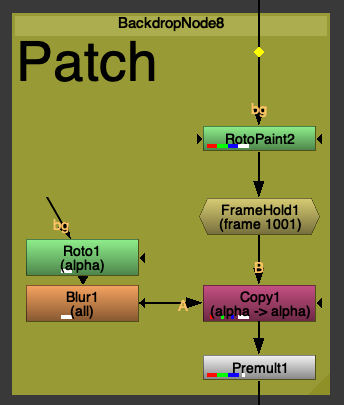
The cleanup patch is then created. This is done in the same way as a normal patch is created, using a framehold and a rotopaint node to remove the part of the shot that you want to cleanup. A roto shape is then used to create the size of the patch, this is then passed through a Premult node to 'cutout' the patch. The patch is currently static throughout the sequence, meaning that it will only cover the fire escape sign for one frame.

The next step is to use the camera data from 3DE to track the patch onto the sign throughout the entire sequence. This done using 3D projection onto a card. The patch created in the last step is fed into a 'Project3D' node, this node is then attached to a 'Card' node. The tracked camera data is also fed into the projection node via a framehold, the framehold has to be set to the same frame that the patch was created on, in this case frame 1001. The card is then attached to a scene node, this node allows multiple 3D elements to be viewed at once in the 3D view. The card then needs to be positioned in the correct place in 3D space, this is done by viewing the locator geo at the same time as the card. The final step is to pass all this into a 'ScanlineRender' node, this node converts the 3D scene into a 2D image, it uses the tracked camera as a viewpoint to render from. Another overscan is also used to match the format of the cleanup patch.

The final step of the cleanup process is to reapply the lens distortion and return to the original format. This is done using the lens distortion node, the node has to be set to 'distort'. The reformat node has to be set to 'Root Format' this returns to the format dictated by the project settings.

The next two images show the process of overlaying the geometry exported from 3DE onto the original footage. The two .obj files are fed into a scene node, as previously mentioned this allows multiple 3D elements to be viewed at the same time. The geo nodes also have a node fed into their image input. In the case of the locators this is a constant node that has been set to yellow, and in the case of the cube a wireframe node. The wireframe node displays the edges of the cube in a different colour to the faces. The scene node is then passed through a scanline render, this uses the tracked camera data to render from.
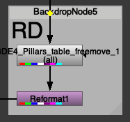
As with the cleanup patch, the final step is to distort the image to match the original plate. This is done using the lens distortion node set to distort and a reformat node to match the original formatting of the sequence.
The image below shows a scene view of, the tracked camera, geo objects and the projected cleanup patch.

Assignment 02:
MoCap Character Comp:
Final Comp v1
Breakdown v1
For this assignment the task was to take a 3D tracked shot and use a combination of Maya and Nuke to composite a 3D element into the shot, 3 variations had to be created.


The image above shows a screenshot of the Maya scene file for the composite using my motion capture character created for the performance animation module. In the scene you can see the camera and the locators produced by 3DE, the camera has all of the animation data that is created by 3DE when the camera is tracked and solved. You can also see a ground plane, this ground plane has been aligned with the points that were tracked on the floor of the sequence. The plane has an aishadowmatte shader applied (See screen right), this allows for the shadows in the final render to be captured and applied over the top of the background image sequence. You can also see a lighting setup using 3 area lights, I used images from the live action plate as a reference for the lighting. You can see a rendered image below, it has a light gray background applied in order to show the shadow, the images are output as a .tiff file, these files can included alpha channels in the data.

After rendering, the next step was to composite the robot into the scene using Nuke. Below you can see a frame from the comp in Nuke and the node graph below that. The first node in the tree under the rendered sequence is a grade node, the node has been labelled 'Luma' this is because the node controls the luminance values of the sequence. In this case it has been used to increase the overall brightness of the robot, this helps it sit in the scene as it more closely matches the lighting conditions of the background plate. The next node is a Lightwrap node, this node ustilises a background image to create a small edge highlight around a foreground image. In this case the node is connected to the background plate using a dot node with a hidden input, this helps the render sit in the scene better as it uses the colour data of from the background on the highlight. The next node is a defocus node, this applies a very small blur to the robot, this recreates a slight out of focus look that matches the other objects in the scene. The premult node then cuts the robot out using the alpha channel, this ensures that the next grade node only effcts the robot as oppose to the whole shot. The next grade node mainly affects the gamma, with the gamma boosted the contrast of the render is reduced, this more closely matches the background plate which has quite a low contrast. The final node in this part of the tree is a motion blur node, this node analayses the motion of the sequence and applies a blur, simulating the blur captured by a camera in the real world. This node allows you to control the blur using a shutter angle setting, adding the blur post render allows you to have a lot more creative control over it as oppose to generating the blur using the renderer. The nodes after the merge node that merges the CG plate over the background plate, undistort the image sequence (done by eye, not using data from 3DE) and reformat the image to 1080p (in order to render the output using non-commercial).


The final step was adding a colour grade. I decied to do this in Adobe Premiere Pro. Using Lumetri colour in Premiere Pro allows you to add basic colour correction and create and control a stylised look for a shot. In this case I used a basic colour correction to boost the exposure and tweak the lighting of the shot and then applied a 'Creative look' that gives the shot a blue, cinematic looking tinge. I also added a small vignette to draw the eye into the centre of the shot.


After recieving feedback during a dailies session, I changed the textures of the robot character to a brighter colour. This change was made to improve the visibilty of the character in the comp as the dark texures meant that details, especially those in shadow hard to make out. Another piece of feedback suggested that I also add a reflection of the character in the TV screen, the process for how this was achieved is explained below.

First I created and placed a plane in the correct 3D space to line up with the TV screen. I also decided to add a green floor and wall to reflect the light from the scene, without this there would be no visible reflection as there would be no light hitting the back of the character.

I then created and applied a new aishadowmatte shader, using the settings seen above the shader only captures specular light.

For more control during the compositing of the shot I decided to render the reflection out separately. To do this I rendered a pass with the TV screen geometery hidden and another pass with all of the characters mesh 'Primary Visibility' disabled. Having primary visibility disabled means that the mesh will still show in reflections and shadows but not appear to be physically in the scene.


The final step was to composite the reflection into the final shot. This was a simple task as the reflection was the only part of the rendered image, I had to add a grade node in order to boost the gamma of the element as the output image from Maya was too dark to see when added to the background plate. I also added a motion blur node to help place the element in the shot. Below you can see the final comp and a breakdown video.
Final Comp v2
Breakdown v2
After recieving feedback on the reflection of the character in the TV screen, I further boosted the gamma of the reflection pass in Nuke, this made the reflection easier to make out and notice in the final comp.
Final Robot Comp and Breakdown
Character with Fire dynamics
For this assignment I wanted to utilise the new Bifrost Graph Editor. The bifrost graph editor allows you to create realistic aero, particle and cloth simulations using a visual, nodal interface. Intially I wanted to create something like a campfire or similar static fire, however after some reseach I discovered a way in which you can use an alembic cached animated mesh as a way to drive a simulation. So decied to use a rig from Truong CG (Link), and motion capture data from the Rokoko Motion Libary.


I first decided to create new materials for the character rig, you can see the orginal in the left image above and two renders of the new materials on the right. The character now has an outer layer of steel with blue and black carbon fibre visible as wear, a middle layer of golden wires and a blue, emmisive inner layer.


Above you can see the two respective Substance Painter projects.

The next step was to aquire and apply motion capture data from the Rokoko Motion Libary onto the character. Due to the complexity of the downloaded rig I was unable to create a working HumanIK character definition for the character, so I removed the rig from the character, leaving only the mesh in the scene. I then used the HumanIK auto-rig function to create a new rig and character definition, I could retarget the motion capture animation onto the character, you can see a playblast of the character in the scene above.

With the motion capture data applied to the character, I could then create an alembic cache of the animated mesh. This .abc cache file allows the animation to be used with the Bifrost Graph Editor much more efficently than a uncached, keyframed rig and mesh. Above you can see the Bifrost Graph window, I used a preset torch flame to create the main part of the graph and later edited various parameters to create a simulation that I was happy with. A read_Alembic node is used to input the cached animation, however a time node has to be connected to this in order to for Bifrost to play through the whole animation, otherwise it only uses a single frame. The read node is then fed into the air source node, this acts as a source for the aero simulation. In the playblasted example the read node is also connected to the burning_geo output, this is to show how the final comp might look when combined with the rendered animation.
Above is a test comp of the rendered character and animation before the fire simulation is added.
Above is another test comp with the rendered fire simulation added. The reflection and shadow passes are still to be rendered.
Breakdown
The image below shows the Node graph of the final comp. You can see how the CG elements have been broken down into different passes, and then composited at different layers. The node graph is broken down in further detail below.

Below you can see a closer look at the CG Plate section of the comp. This section includes the raw render of the Cyborg character and the adjustments added to the render to better place the character in the shot. The 'Grade1' node is used to bring the luma values of the render closer to that of the background plate, as you can see the raw render was very dark in comparison to the bg plate. The next node, 'LightWrap1' helps place the render in the shot. The node uses the colour data from the bg plate to wrap light around the edges of the render, this helps emulate the soft edges you see around the edges of an object caused by the reflection of the light of the surroundings. The 'Defocus1' node applies a slight blur to the render, this is to emulate how the bg plate appears slightly out of focus. This helps set the render in the scene as the raw render is perfectly infocus, which would be impossible to capture using a real video camera. The 'MotionBlur1' node anlyses the render and applies a motion based on the movement of pixels and settings outlined within the node. This helps set the render in the shot as fast moving objects become blurred when captured by a rolling shutter. The 'Exposure2' node is a keyframed grade node that darkens the CG plate when the fire ignites, this is to simulate the camera metering for the fire, rather than the background.


The images below show a closer look at the shadow pass of the Cyborg character. In this example the rendered shadow matched the bg plate well so no changes had to be made to it, however rendering a shadow pass seperately gives you a great amount of control over the blending of a CG element. Matching shadows of a CG plate to a bg is very important in getting an accurate result when compositing.


Below is a closer look at CG Fire section of the comp. One of the most noticable parts of this section is that it is merged back over the background plate twice. This is because the render of the fire doesn't have the CG character in it so when it is merged over the bg plate all of the fire appears ontop of the character, this doesn't look very good as in 3D space the character becomes completely engulfed by flames. The bottom part of this section shows how I sperated the flame into the parts that appear infront of the character from the parts that appear behind it. A roto node is first drawn around the parts of the fire that would be infront of the character in 3D space, this is animated throughout the shot to follow the character and add some dynamics to the appearence of the flames. This is then passed into a 'Fractal_Blur' node, this is a custom node that adds a blur to the edges of a roto using a fractal noise pattern as a mask, this gives a roto shape a more organic look, it is also useful when rotoscoping trees. The top part of this section shows the nodes added to control the look of the render. The 'Exponetial_Glow' node is an custom node from Nukepedia, this works in a similar way to the default glow node in Nuke but produces more accurate results and gives you a greater control of the look. The next node is a motion blur node, this not only helps blend the render in with the background plate but also improves the look of the render, as without the motion blur some of the voxels of the fire simulation can be clearly seen, this is due to the detail of the simulation when it was computed. The final node is a grade node, this node is used to bring down some of the highlights in the flames.


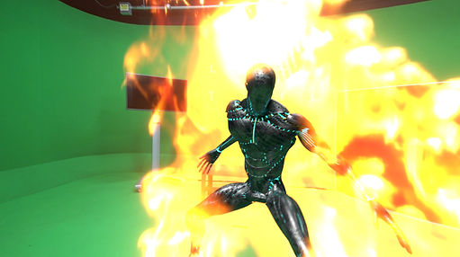
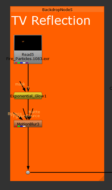
Next is a closer look at the TV Reflection part of the comp. This is a render of the reflection of the fire caputred by the TV screen, this was rendered using an AiShadowmatte material set to capture specular reflections and not shadows. The render is merged over the bg plate using the 'plus' operation, this is because a reflection is additive. The reflection has an exponetial glow applied to show the intensity of the light being given off by the flames. Another motion blur node is used here to set the render into the shot.


The images below show the Cyborg Fire Reflection section of the comp. This section applies the light reflected onto the surface of the character, this layer helps the character appear to be on fire, without this reflection the character appears to be very seperate from the fire. Similar to the other fire elements of the comp this render has a glow, motion blur and grade node applied. The difference these nodes make is show by the lower image.


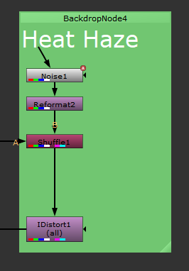
The next section of the comp is the Heat Haze effect. This emulates the distortion effect that heat produces in air. This effect is created using an 'IDistort' node that is being driven by an animated noise. The pipeline is as follows; an animated noise node is passed into a reformat node, this matches the resolution of the noise to the project settings, this is then passed into a 'Shuffle' node, the shuffle node also has the main pipeline of the comp as an input. The lower image shows the parameters of the shuffle node. The noise is the B input and the main comp is the A input. The red and green channels of the B input are ouptut as the forward.u and forward.v channels, this allows the data output by the animated noise to be accesed by the IDistort node alongside the rgba data of the original comp. The output of the IDistort node is then merged back over the main comp. This merge node has the 'mix' parameter keyframed so that the effect isn't present throughout the whole shot.


The final parts of the comp is the 'LensDistortion' node applied to the comp, this roughly re-applies the lens distortion of the live action plate, as the imported background sequence is undistorted from the 3D-tracking process. And the animated exposure change on the background and CG character plate, this is applied at the top of the comp staight after the read node of the live action sequence.


The final step was to cleanup the pink tracking markers in the background of the shot. To do this I focussed on the live action plate by viewing before any of the CG was added. The cleanup is broken into 3 sections, the first section covers up the main bulk of the markers, however there is one that is occluded by the TV screen at the begining of the clip, the second section handles the covering up of this marker. The final section re-covers the TV screen as the patch for the second marker ends up ontop of the screen.

Breakdown Video
Final Comp
Invisible Effects Shot
During this assignment I wanted to create a shot that didn't have anything be immediately recognisable as CGI. As the live action plate was shot in a studio room I decided to create some assets that could be found in a studio setting, such as a camera and a lighting setup.

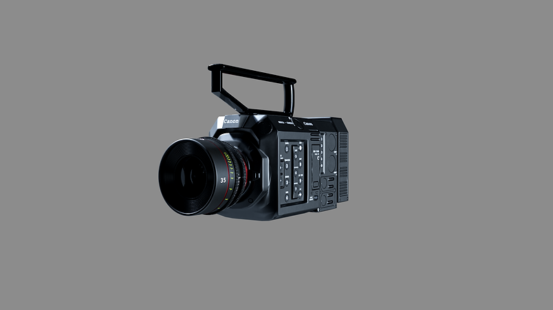
First I created a cinema camera and lens, the lens is based on a 35mm Prime in Canon's cinema line and the camera is based on a Canon Eos C500 Mark III cinema camera.

Next I modelled and textured a tripod and tripod head. I then retextured an old table asset and used a free plant model from turbosquid.

I then consructed a 3D scene using these assets, in a setup you might find in a studio setting. When rendering I decied to render as many passes as possible, this was to give me more control when moving into Nuke. The assets were rendered out as induvidual passes, along with seperate shadow passes, this allowed me to control the colour correction of the objects induvidually.

Above you can see the Nuke script for the final comp. The shadows are the 'lowest' layer, with the objects being merged over these. The main changes done in Nuke was matching the black levels, especially for the camera. This is done by utilising a grade node. First you colour pick the darkest area of the CG plate and set this as the 'blackpoint' parameter, you then colour pick the darkest area of the live action plate, in this case the TV screen (making sure to avoid any reflections of the surroundings), and setting this as the 'lift' parameter. As with the previous comps most of the nodes are there to better place the renders in the shot.
Breakdown Video
Final Comp
'Lurker' Comp
Below is a still image and breakdown of a work in progress composite of a 'lurker' rig from the Starcraft series created by Truong CG Artist (Link). The footage was filmed using a Nikon D7100 at Turners View, Richmond.

The above stills are from a longer animated sequence, below is a playblast of the animation of the lurker viewed from the tracked 3D camera.
Below is a screenshot of the node graph in Nuke, this is currently a test comp using single frames to test out techniques.
