Unity Materials

A range of different materials created in Unity using the Standard Shader.

This first shader has a texture attached to the emission value of the standard shader.

The second material has a checker pattern applied to the Albedo (Or diffuse) channel, and a crumpled paper normal map applied to the normal channel. The normal map creates an illusion of extra depth and detail on the surface of the cube.
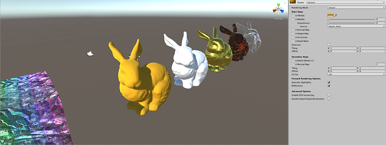
The third material has an orange colour applied to the albedo channel, and a smoothness value of zero. This results in a very matte finish.

The fourth material is similar to the last one, however it has a smoothness value of one. This results in a much glossier finish.

The fifth material has a gold colour applied to the albedo channel, a metallic value of one and smoothness value of around 0.7. This results in a finish that emulates gold.

The sixth material has the rendering mode set to transparent and an alpha value of zero in the albedo channel. This results in a finish that emulates glass.

The last material has an unlit (or Silhouette) shader applied. This means that the material is not affected by the lighting system in the world.
Particle Systems

Particle systems in Unity can be used to create various effects, ranging from fire, to snow and rain.


To create the fire effect seen above, the following settings are used with the particle system. The changes made to the core settings involve changing the start speed 0, so that the particles would only be affected by a force applied after the particles are born. The start size was also changed, to a random value between two constants; 1 and 3. The shape used for the system was a cone. Another setting that was applied is a force
over lifetime. This gives the flames some randomness and also gives them some vertical velocity. The settings are between two constants, with the X axis between negative 0.2 and positive 0.2 and the Y axis between 0.2 and 1. The colour over lifetime has also been changed, the gradient has been edited as seen above, with the alpha starting at 0 increasing to about 0.7 and back down to 0, giving a pulse effect to the flames, the colour is also changing over time from yellow, to orange to red. Finally the material that is attached to the particle system is using a cloud as and albedo texture, the material is also set to additive.


To create the snow effect seen to the left, the following settings were used. In the core settings the start speed was set to 0, the start size set to 10 and the gravity modifier was set to 0.9, the last setting was changed so that the snow would fall downwards. A large box shape was used as the source for the emission. A force over lifetime was also added on the X axis, this gives the snow some randomness as it falls. I also enabled the noise option on the particle system, some of the settings were changed resulting in the image seen in the noise drop-down. This is applied to the particles as they fall giving the snow more randomness. Finally the material
used has a snow texture applied to the albedo and the shader is set to additive.


The images above show the trail renderer component. This can be used to create a trail that follows a game object around ( e.g. a 3D mesh or particle system). The trail above has a material with a rainbow texture added to the albedo path.
Particle Systems 2

The image to the left was created using a particle system using a mesh as a guide for the shape of the emitter. To add variation to the effect I added a scrolling noise effect and a small trail to the particles.


Introduction to Coding


As an introduction to coding and creating scripts we created a script that could be edited inside the unity editor to display a name when the script is ran. In the top image showing the script you can see the Name and Surname strings have been made public, this is what allows the script to be edited from inside unity. Below that you can see the code that displays the text in the console.
Procedural Art With Scripts

To start I created a large grid of circle sprites, using the snap settings to ensure that they're all spaced evenly. Each sprite has the SizeEffect.cs script attached to it.

The next step was to create a value to input into the scale of the sprites. To do this I created a float value of 0.1, this was then input into the local scale of the sprite using the previously created float value as the x,y & z values of the scale.
The image below shows the result of running the script.


Next, I added a line of code that changed the float value (size) from a static value of 0.1 to a random number between 0 and 0.3.
The result of this can be seen below. The scale of the sprites has been completely randomised.


Finally I added another line of code that uses the randomly generated size value to change the colour of the sprites.
Below you can see various results of this, with the size value being input into different R,G,B values.


Underwater Environment
Assets
I was provided with most of the assets that are used in the scene, including the character, rocks and plants.

I was provided the mesh for the ocean floor, however I downloaded and applied a sand texture. This texture included a normal map, the normal map gives the illusion of waves and dents in the surface of the ocean floor.


I also modeled two extra assets for the scene. The first of which was a tall rock tower, I decided to model this as I felt the provided assets were lacking verticality. In the second image below you can see the asset inside Unity with a downloaded rock material applied.


The second asset I modeled was a basic submarine, I created a low poly mesh and concentrated more on creating a detailed texture. In the top image you can see a wireframe of the model. The second to the fourth images show the texturing process using Substance Painter. To start I applied a Painted Steel Smart Material and changed the colour to a dark gray. I then added a fine rust material and applied a subtle scratches smart mask onto this to create the rust pattern. Finally I added another layer, and using various scratch and mold alpha maps added detail to the height and normal maps to create a more damaged look. In the final image you can see the submarine inside Unity.


Layout
For the layout of the level I decided to create a cave around the starting location of the player character. I then created a border using large rock pieces to limit the playable area, I then filled in the remaining space with other smaller rocks and plants. I also positioned the submarine directly in front of the cave exit.

Post-Processing & Particle Systems
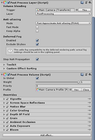
To create an underwater feel to the level I used a combination of post-processing effects and fog. The first three images below show the difference between the raw appearance, the appearance with post-processing effects applied, and the appearance with fog applied too. There are three effects that have the most impact on the look of the level, these are the vignette, the colour grading and the bloom effect. The vignette helps give a sense a depth by reducing the field of view with an outer black edge, the colour grading gives the scene a higher contrast, greener appearance and the bloom gives a boost to the look of the lighting and also adds some lens dirt. The fog also has a large affect on the look of the level, it gives a great sense of depth and mystery as the players visibility distance is greatly reduced. The fog is also dark blue in colour, this creates an illusion of being in deep water.



To help create the underwater feel I also added several particle systems. One system produced bubbles from the rotor of the player character, another produce ambient bubbles, this was also attached to the player character so that there was an illusion of bubbles in all parts of the water. The final system was positioned on the side of the submarine to simulate a leak. The first system was attached to the body of the player character, the emitter was cone shaped and was positioned inline with the rotor mesh. The particles have negative gravity so that they float upwards, have a small initial speed and the particles size is random between 0.05 and 0.5 to create a variation. The second system has a very small negative gravity so that they float upwards slowly, range in size between 0.025 and 0.1 so that they appear much smaller than the bubbles produced by the rotor. They also have a gradient applied to the alpha channel over time, so that they fade slowly out, and the emitter is a box shape producing a large coverage. The final system has a small start speed so that spread slightly, a large constant force in the Y - axis so that they appear to be flying upwards with force and a small range in size to provide variation.


Level Flythrough
Sorting


The title screen seen above is made up of 14 different elements. To create the final image the sprites have to be sorted. To do this you have to create and use sorting layers and the Order in Layer option. Sorting layers allow you to sort assets by type. throughout your project. The order in Layer option allows you to change what appears on top of or below other assets, for example an image with the order in layer set to 0 would appear below an image with the order in layer set to 1 or 2.
Y - Axis Sorting


Y - Axis sorting allows the sprites to be sorted using the world position, as oppose to the layering technique shown previously.
Masking


Masking allows you to hide and reveal parts of sprites using another sprite as a mask. Above you can see the affects a mask shaped like the bee works, the two bushes have different mask interactions. This means that the bee shape reveals part of the sprite or hides parts of the sprite depending on where the bee is.
Advanced Camera Settings


The image above shows how a camera renders when the rendering mode is set to 'Don't Clear'. This rendering mode means that the camera ignores the background and keeps displaying the previously rendered frames.

The images below show how you can combine the views of two cameras as a composite. The view in the bottom left is a camera set to 'Don't Clear', this ignores the red background colour. The view on the bottom right shows the view of a camera with the 'culling' mode set to nothing.


The images above show how to produce a split screen effect. This uses two cameras in the same world position, but the viewport settings are modified so that they appear half the size and side by side.

The above image shows a 'mini map' style effect. To achieve this there are two cameras in the same world space, and similar to the split screen effect one of the camera has different viewport settings so that it appears small in the bottom left of the scene.

Shaders


To create a shader using the lightweight render pipeline, you have to use a shader that uses the shader graph. Once created the shader has to be selected by the material that you want to use it on.
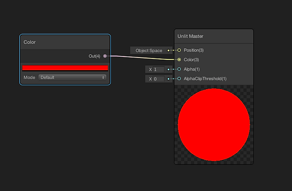
The images below show a basic shader with a colour node attached. The colour node has been converted to a property so that it can be changed in the material settings.


These three images show the process of adding a slider to the shader. With the slider node added you can convert it to a property so it can then be edited via the material.
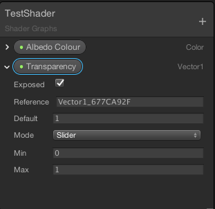


The above two images show another way to control the transparency. Using a split node so that the A (alpha) channel of the colour is input into the Alpha channel of shader. This means that the transparency can be controlled by the alpha channel of the colour selection in the material.

Below you can see the difference between an unlit shader and a lit shader. The unlit shader has no shading and is not affected by the lighting present in the scene, whereas the lit shader is affected by this lighting and areas of shadow can be seen on the rabbit.


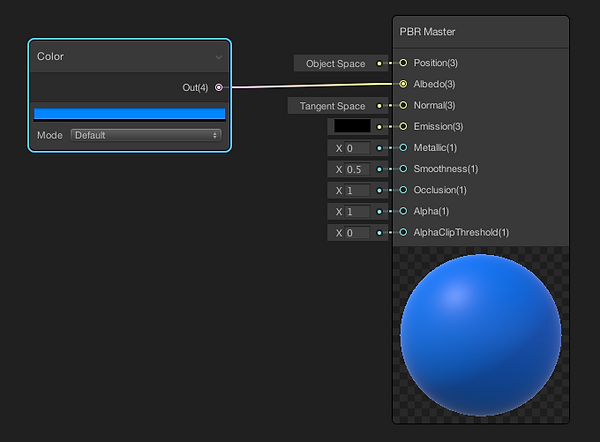


The three adjacent images show how the 'Add' node works in the Unity Shader Graph. You can see that two colour nodes are input into the Add node and the result is output into the Albedo of the shader.
The two colour nodes have been converted to properties, this means that they can be edited from the UI in the Unity editor.
The result of the example graph can be seen to the left, as you can see the two colour values have been added together.


The above images show what happens when you replace the 'Add' node from the previous graph with a 'Multiply' node. As you can see the two colour values are multiplied by each other, for example when the blue colour is multiplied by a pure black the output is also black this is because the RGB code for black is 0,0,0. However when the blue is multiplied by the grey it is slightly darkened, and when multiplied by white remains the same.
The following images show what a 'lerp' (Linear interpolation) node does in the same shader graph. The lerp node uses a third input. This input is a slider labelled 'Transition' that has been converted into a property. The lerp node uses the value given by the transition shader to mix the two colour values together.
The images below show what different Transition values do to the resulting output. A value of 0 results in only the blue colour, whereas a value of 1 shows the pinky colour, and a value of ~ 0.5 shows an even mixture of the colours.


The images to the left show the result and the graph of when a 'Position' node is added into the 'Lerp' node. The position node first needs to be passed through a 'Split' node in order to isolate the Green channel data.
The resulting shader uses the position data of the model it is applied to to transition between the two selected colours. The position node has different space settings, the example image is set to World Space. This means that when the model is moved the shader changes in relation to the new position. If it was set to Object Space then moving the model would have no affect on the shader.
The images below show the workflow in creating an animated Grass shader. The first step is to attach a 2D texture to the shader, you can see in the third image that just attaching the RGBA output of the texture to the albedo of the shader results in the shader having no transparency. To fix this the A output of the texture needs to be attached to the Alpha of the shader, in this case the 'double sided' option also needs to be applied.


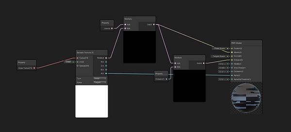
The images to the left show how to add colour to the texture. A multiply node with a colour node that has been converted to a property is added, these nodes are placed between the colour output of the texture and the albedo input of the shader. This allows you to pick a colour of your choice to apply to the texture.
However the result isn't perfect as the emission value of the shader also requires changing to get a strong colour showing. Another multiply node is added, along with a slider node that is converted to a property. These nodes use the output of the previous multiply node and inputs its result into the emission of the shader.


The following images show the final stage in creating the shader, animation. A UV node is used to drive the animation, the node is split so that the individual U and V channels can be accessed. A time node is used with a multiply node to control the intensity of the effect, this multiply node is input with a add node along with the U channel from the UV node, this animates the grass along the x-axis.
The final image shows the completed shadergraph. This uses the V channel of the original UV node to control the axis on which the grass sways. A slider has also been added to allow control of the intensity of the animation from inside of the Unity Editor.
The images to the right show the shadergraph and resulting output of a phong shader.


The images to the left show the shadergraph and resulting output of a toon shader.

The images to the right show the shadergraph and resulting output of a Fresnel shader.


The images to the left show the shadergraph and resulting output of a fog shader.

The images to the right show the shadergraph and resulting output of a normal vector shader.

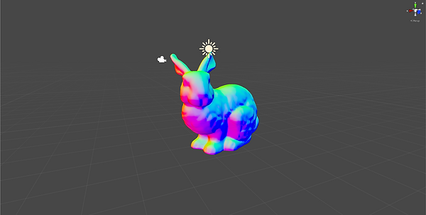

The images to the left show the shadergraph and resulting output of a shader with a normal map applied.
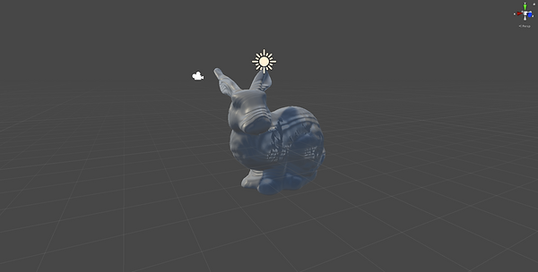
The images to the right show the shadergraph and resulting output of a shader with a vertex displacement applied.


Optimisation
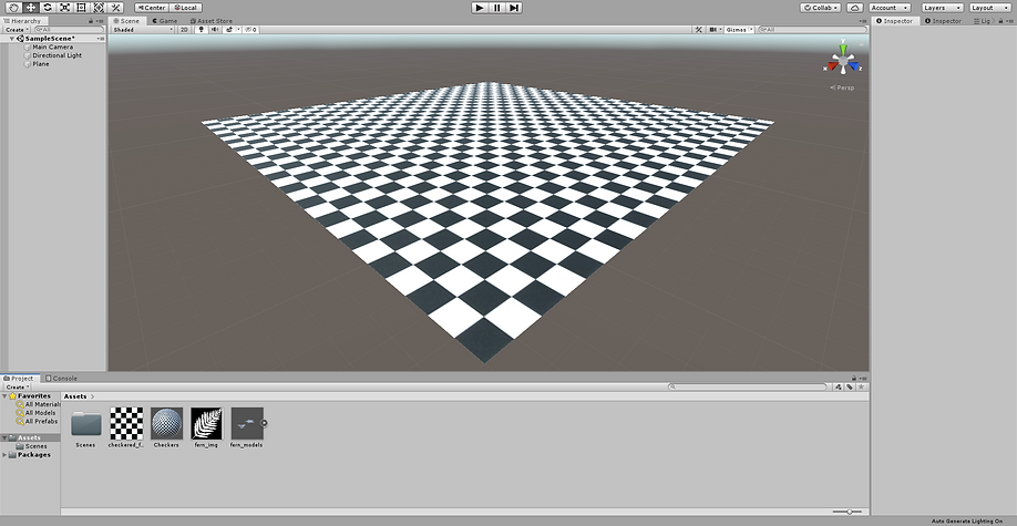

The images above show a technique called MipMapping. This is where a texture image is scaled depending on its distance from the camera, this results in a smooth look to the texture as it gets further away. The top image has MipMapping enabled whereas the bottom image has MipMapping disabled. With MipMapping disabled the texture appears jagged and rough.


The images above show the difference between different texture resolution settings. Using a lower texture resolution means that there is less graphical computation required to render an object, this improves performance. Using a low texture resolution e.g. 32px, results in a big performance gain, however the quality is considerably reduced, using a higher setting e.g. 512px results in a higher quality, however would have an adverse effect on performance. Finding a good midpoint between quality and performance is key to good optimisation.

The image above is an example of baked lighting. Baked lighting is pre-calculated lighting that isn't dynamic, this helps performance massively as it allows complex lighting data to be saved for static objects. However if an object with baked lighting is moved then the lighting remains in place.


The above images show how an LOD group works. LOD (Level of Detail) groups are a way of optimising a game world by replacing high detail meshes with lower detail meshes depending on an objects distance from a camera. You can see that when the camera is close to the tree the LOD 0 mesh is displayed, this is a high quality mesh, when the camera is further away the LOD 1 mesh is displayed, this is a lower quality mesh than that of LOD 0, finally when the camera is even further away the mesh is culled completely.


Scripting
In the adjacent images you can see a script and its result in the Unity console. This script uses a counter to limit its outputs to 10. The function itself simply adds 10 to itself over and over again.


The two scripts above a almost identical to the first example, however they use a different maximum counter number to limit their outputs and use different functions, for example, adding 4 and dividing by 3.


The adjacent images show a script that takes an age input and outputs what age group that the ages falls under. The script utilises the 'If' and 'Else If' functions. These functions allow you to build up a logical progression covering multiple inputs and outputs.


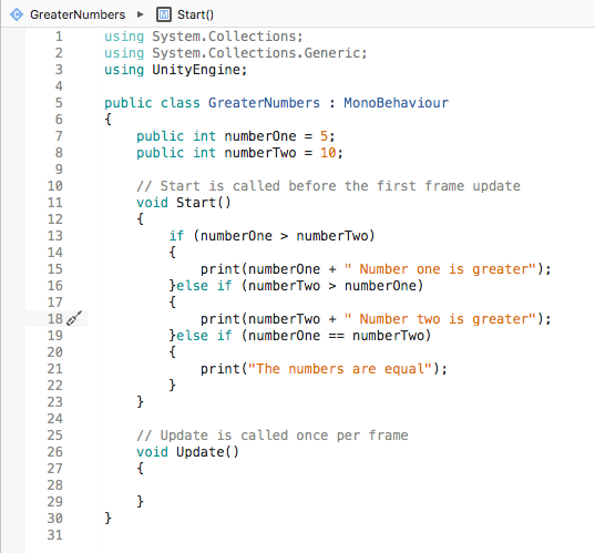
The images above show three different outputs from three differing inputs. The script can be seen to the left. The script uses two public numbers and works out which one is biggest, it does this by first seeing if numberOne is greater than numberTwo, if it is, it prints the number and says that Number one is greater. If it isn't greater it sees if numberTwo is greater than numberOne, if it is, it prints that number and says that Number two is greater. If it's not it sees wether the two numbers are equal to each other, as this is the last option this line is not necessarily needed as a lone 'else' function would have the same result, if they are equal it says that the numbers are equal.


The images above show three different outputs from three differing inputs. The script can be seen to the left. The script uses a public string to tell the user if a day is a weekday or at the weekend, and asks the user to check spelling if no matches can be found. It uses a similar premise to the previous script using 'If' and 'Else' statements.

These images show the result and script of a random colour assigner. The script uses a random number generator to assign colours. A number is generated between 0 and 3, this number is then used with several 'If' statements that assign a colour depending on the number that was generated.

The video above shows how the basic movement script to the right works. The script uses key inputs to drive the translate function of the cube, the speed and direction that the cube moves in is controlled by the public speed value. The speed value is used in the X or Y values of the translate function depending on what direction arrow key is pressed, a minus sign is also added to reverse the direction of movement. For example a positive value in the X axis would move the cube to the right, whereas a negative value would move the cube to the left.

The three videos above show three different examples of small games that are built using all of the skills learnt during the practice exercises. The first example only uses a simple movement script that uses two values to control the movement speed and rotation speed. The second example uses a lot more different scripts, there's another simple movement script, a HUD element that is activated upon an item being picked up, a script to fade boxes when they are passed over and a script that controls the door depending upon an item being picked up. The third example uses two scenes, the first scene has a menu and a scene that contains the actual game. The game uses a script to spawn enemies in a random order in three lanes, a 'Try Again' text that appears when the player is hit and a movement script that forces the player to stay in three lanes.