Week 1 - Intro To Nuke


The above images show how a background and a foreground image can be combined using the Merge node.


The two images above show how multiple foreground images can be combined with a background image. Multiple Merge nodes are used, one at each step.


The two images above show a more complicated Node graph. In this example only one image is being composited onto the background, however this image is also having several additional changes made to it. having the Merge nodes in the correct order is key.
Week 2 - Roto
Rotoscoping is a key skill in VFX, it allows various parts of images and video clips to be cut out and later composited in a different way. The roto node is used in Nuke to perform this process.

When the roto node is active, there are several ways that you can draw the matte onto the footage. The bezier curve (Top green sweet), the B-Spline (Other sweets), the cusped bezier (A bezier that can only do straight lines), the rectangle and open spline (don't need to form closed shapes), are all the drawing shapes available in Nuke.

To use the alpha channel created by the roto node, you need to use a copy node. This allows you to use the alpha matte with the original footage, that might not have an alpha channel by default.


The above images show the resulting alpha matte created by a roto node. The top image shows an overlay that you can view when using the roto node, the second image shows the alpha matte created and the final image shows the feather tool, the dotted line can be manipulated to feather the edge of the drawn roto mask.


The above node graph produces the second image above. The roto node is used to cut out the sweets, a grade and a glow is then applied to the cut out sweets, this changes the appearance of the image. A blue constant is then added to the image using a Merge node, the blue is attached to the B input of the merge node so that it acts as the background, and the sweets attached to the A input, to act as the foreground.
Animating Roto


The above images show a simple workflow of creating an animated colour grade using the roto node.
The above video shows the final result. Animating roto in Nuke is done the same way as animating anything else within Nuke. As nuke uses an auto-key system all you need to do is create a roto on the sharpest frame you can find and scrub through the footage manipulating the roto shapes where needed. It is best to avoid keyframing roto shapes on every frame as this can result in boiling. Boiling is when a roto shape can be seen constantly changing very slightly, this results in a bubbling look on the footage.
Week 3 - Advanced Roto
When dealing with more advanced shapes that require rotoscoping, it is common practice to use multiple roto shapes as oppose to using one that would need to be updated every frame, which would result in boiling.

The above image is an example of this, the thumb roto is made up of three individual roto shapes. These shapes all overlap each other, this means that there won't be any gaps in the roto (see image below).

The image below shows the first finger being rotoscoped using the same technique.

Below is the result of using three roto shapes per finger and three for the palm.
Below shows an example of a full body roto, with an occlusion. The occlusion is dealt with by creating another roto shape over the pillar and using a merge node set to 'Stencil'.
Week 4 - Keying
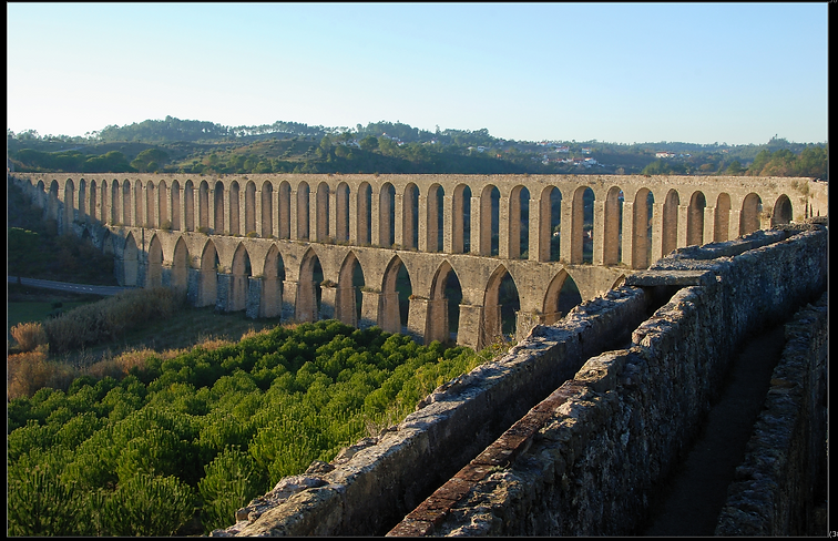

The above images show a simple sky replacement. The top image is the original image and the bottom image is the result. To achieve this a process called Keying was used, in this particular example a Luma key was used. This uses the luminance data from an image to remove parts of the image depending on its brightness/darkness.


The first image above shows the Alpha matte created by applying a luma key to the original image (The luma key node is inverted in this example). In the top image you can see in the top right corner an area that hasn't been removed, to deal with this and some parts that have been incorrectly masked, some garbage mattes are created. These are roto shapes that cleanup the original key.

The image above shows the result of the Luma key and garbage mattes.

The node graph above shows the final nodal tree of the sky replacement. You can see the Luma key that has the garbage mattes merged with it, the created alpha is then applied to the original image using the copy node, this is then fed into a Premult node which actualizes the alpha channel of the image. A light Wrap node is then used, this cleans the edges of the alpha created by the keying, finally the sky image is merged with the keyed original image.
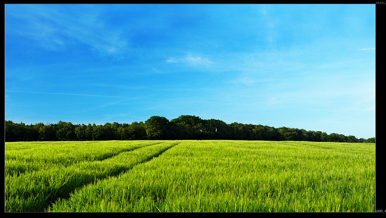

The images above show another example of a sky replacement. In this example an external node was used, the colour dilation node. This node is used in a similar way as the light wrap node, to clean up the alpha created by the keying process. To use the node the text below is simply pasted into Nuke, this creates the node which can then be added to the node tree in the normal way.

The nodal tree of the above sky replacement:

Another commonly used method of keying is Chroma keying. This uses colour to create a matte as oppose to the luminance values used by a luma key. Chrome keying is used most commonly with footage captured using a green or blue screen, the example below shows the final composite, with the two plates below.


The image below shows the nodal tree for this process. You can see that two keys were used, these keys have also been labelled as 'Base_Key' and 'Garbage_Key'.

The base key is used as a starting point, it keys out a small amount of the green screen while retaining as much detail in the hair as possible. The garbage key is used as a much more aggressive key, this also has the 'Filter Erode' node applied to it, this gives the created matte a much harder edge. The garbage key is then merged with the base key using the 'mask' operation, this only shows the areas of image B that overlap with the alpha of A. The final part of the nodal tree is a garbage matte (Roto1 node), this cleans up the edges that are left over from the chroma key. Another external node is used in the tree, 'Despill_Madness' this node removes the green tint cause by the greenscreen that bleeds onto the edges of the actor. The final operation is to combine the images using a Merge node.


Week 5 - Advanced Keying

The exercise this week was to key the above image. Building upon the skills learnt in the previous week, using the keylight node as well as the key mix node, the image below shows the final result.


The first step was to reduce the noise in the image, using a noisy image when keying can result in a bad key as the colour values aren't very uniform. The Denoise node in Nuke takes care of this problem.
The next step is to build up a key by sampling various parts of the image, this is to keep the detail of the frilly parts of the costume in the final key.

The image above shows the node graph of the multiple keys. To combine these different keys the Kyemix node is used. This node uses a roto shape to define the area of key to combine with the previous key, this slowly builds up the alpha, retaining detail in important areas. Below is the alpha channel of the image at this point.

The key is still not complete at this stage as there is a large part of the image that hasn't been removed by the chroma key. To get rid of this and complete the keying process a garbage matte is used, this created using a roto shape, or in this case two roto shapes for either side of the image.


The final step is to apply a Despill node, Premult the image and merge it with a constant background. The Despill node removes any green light that has spilled onto the actor from the greenscreen. Premultiplying the image allows for the alpha channel to be used and appear transparent when combined with another image.


The image below is of the final node graph for the completed key.

Tracking
Tracking in Nuke is a way of matching the motion of an composited object (Roto shape or another image/video) with the motion of the original video. When you add the Tracker node and a track, a box appears in the viewer, this is the tracking point. The inner box detects a pattern and the outer box is the search area, this searches for the pattern dictated by the inner box. You can see in the bottom image the area tracked in this shot, it has a distinctive pattern and high contrast which means that it is easy to track.
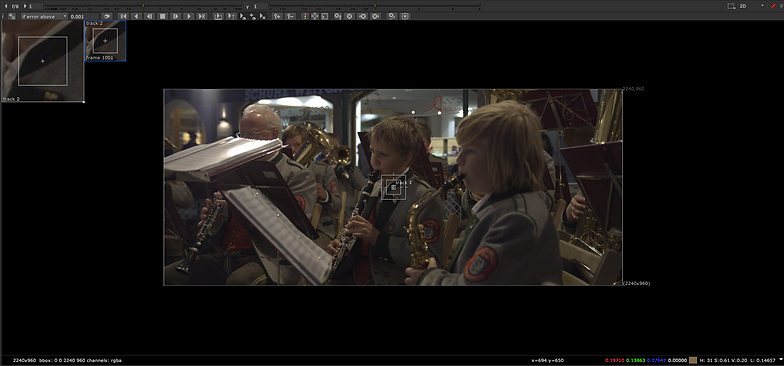

The toolbar below also appears when using the tracking node. This allows you to control the tracking process, to begin the track you click the play forward button, this tracks forward through the video and tracks the point you previously defined. The traffic light symbol displays each frame of the track and assigns it a colour depending on the quality of the track; as seen below.

The final part of a simple track is to set the transform setting in the Transform tab to 'match-move 1-pt', this tells Nuke that one tracker was used and to output the transform data of the track.

Using one tracking point only allows you to track the transformation of a video, to be able track the rotation of a camera through a scene you need to use two tracking points.


For this to work you have to check the 'R' box in the tracker settings, as well as set the transform setting to 'match-move 2-pt'. The resulting track (using a roto shape to illustrate) can be seen below, along with the node graph.

Another way form of tracking in Nuke is Planar tracking. To do this you have to create a roto shape that follows a flat part of the video, in this example the windscreen and number plate of a car are used. The planar track normally has to be edited by hand to cleanup the track, when the track is suitable the data can be output into a CornerPin2D node.


The video below shows the final result of two planar tracks, the first of which applies a colour grade to the windscreen, and the second which composites a custom number plate on top of the original. The node graph is also shown below.

Grading
In Nuke the Grade node allows for images colour and luminance to be manipulated. This is key when compositing as the colours of non-original elements need to be matched to the colours and lighting conditions of the original plates.

The above image shows a green screen plate that has been composited onto a background plate, the green screen footage is a lot warmer and more saturated than the background plate, this is where a grade node will help to blend the two plates together.

The above image shows the affect of the grade nodes being applied to the green screen plate. The image below shows the Node graph for this.

In the Node graph you can see that there are multiple grade nodes being used. The first is called 'LUMA', this node focuses on the brightness of the image, using the luminance channel in the viewer the luminance values of the green screen plate can be altered to match the background plate. This is mainly achieved using the multiply, gain, lift and gamma attributes of the grade node. The second grade node is called 'EdgeLight' this alters the luminance values again, but has a roto shape applied as a mask, this limits the affect to a certain part of the image as defined by the roto shape. In this case the shape applies the grade to the left side of the green screen plate, this is to simulate the light source that is coming from the windows in the background plate. The next node, labelled 'Colour' deals with the intensity of the separate Red, Green and Blue channels. The green screen plate is a lot warmer than the background plate, this means that the Red channel needs to be reduced and the Blue channel increased, the green channel can also be modified to better match the colour. The final node used is a Saturation node, this controls the overall colour saturation of the image.
Animating the Grade Node

In the above image a small patch has been tracked into the shot to cover a mark on the floor, at the start of the sequence the patch matches the colour, but as the sequence progress the lighting changes meaning that the patch becomes visible. To correct this and seamlessly blend the patch with the background plate a grade node is used, the node however needs to be animated to follow the lighting changes.

You can see the key frames applied to the grade node in the timeline of the sequence above. The multiply channels values change throughout the sequence in order to match the brightness of the patch to the brightness of the background plate.
Using A Luminance Key As A Mask

A luminance key creates an alpha based on the luminance values of an image, this alpha can be used as mask by the grade node. The image below shows the alpha created by a luminance key, the key is highlighting the bright, highlighted areas of the image. The image below the alpha channel shows the result when a grade node is applied using the alpha as a mask. This is a strong example of what this technique does, but a more normal use of this technique is boost the highlights of an image, this is useful when simulating lighting conditions of a background plate.


Using Multiple Masks and Grade Nodes
The image below shows the result of multiple grade nodes being combined with masks to change the colours of different parts of a shot. The Node Graph of this can also be seen below.


Grading Challenge


The goal of this exercise was to grade four elements onto a background plate. The images above show the original image and the final graded image. The image below shows the elements before the grading.

The node graph below shows the different grade nodes that were used throughout the comp. The content below shows the workflow for grading the statue, this workflow was used on all of the elements.

The first step was to match the luminance of the statue to that of the background plate. The images below show how this was done. The first image shows the result of the 'LUMA' grade node, this brings the luminance of the statue more inline with that of the background plate, but it still doesn't sit 100% correctly in the luminance channel. This is where the 'ColorLookup' node is used, this allows you to change a very specific range of luminance values in the image. In this case the darkest parts of the statue were made even darker to match the darkest parts of the background plate.
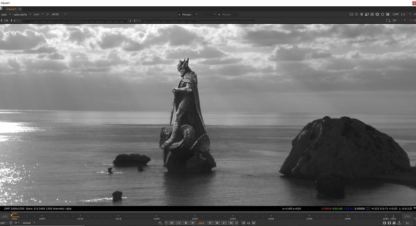

The next step was to change the colour of the statue. The background plate is very blue, this meant that the statue had to have its blues boosted and its green and reds reduced, this was achieved by using the multiply attribute in the grade node, by ctrl + clicking on the colour wheel that appears next to the attribute the individual colour channels can be controlled. This grade helps the colour of the statue match that of the background plate, however the image is over saturated and the lighting does not match.

To fix the problem of the mismatching lighting conditions I used a luminance key to bring up the highlights on the edges of the statue. Below you can see the alpha channel and resulting grade.


The final step was to match the saturation of the statue. A saturation node was used to do this, the saturation was decreased. This final step makes the statue blend with the background more completely than just with a luminance and colour grade.

The castle was the most challenging element to grade in this shot, because it had several different shades to it that were caused by the lighting conditions in the image, these conditions did not match the background plate at all. To deal with this I first matched the colours of the castle to itself. You can see the node graph and the progression of the grade below.
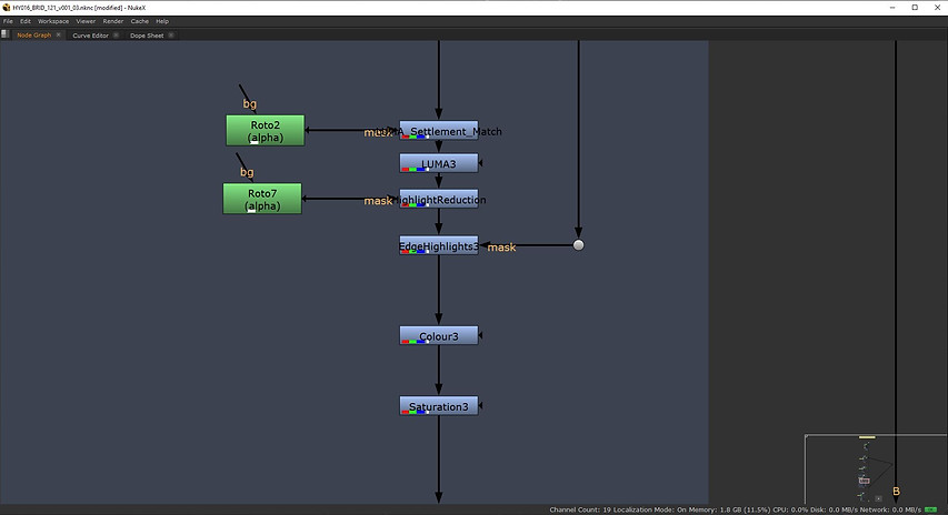


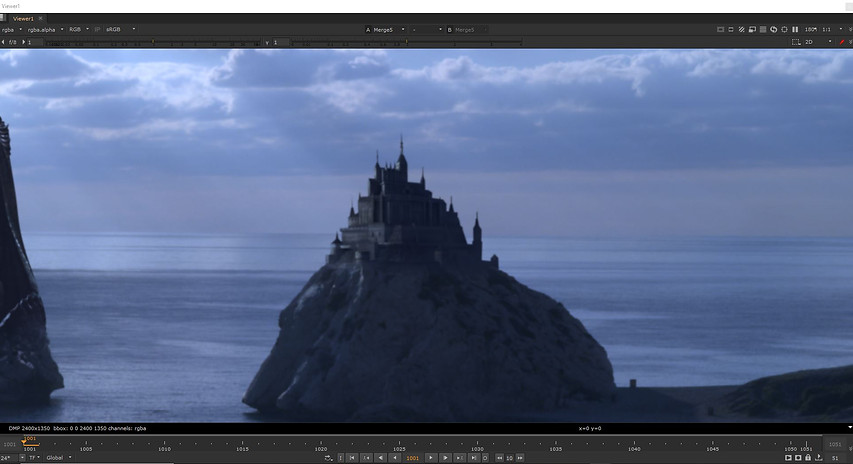
Cleanup and Patch Repair
Cleanup and patch repair is used in a lot VFX shots, it is used to remove things such as tracking markers and other unwanted objects or people from a shot. For example in the shot below the tracking markers would need to be removed before the shot could be keyed.


The Node graph above shows the technique used to remove the markers. RotoPaint nodes are used in conjunction with tracker nodes, the rotopaint nodes can create clean patches using the clone brush, these patches are then animated with the data captured by the tracker nodes.


The images above show the rotopaint toolbar and the clone brush. The rotopaint toolbar contains several different tools, a shape creation tool much like the one found in the roto node, a brush, clone brush, blur and sharpening tools, as well as dodge and burn tools. When the clone brush is selected the two icons above appear in the viewer. The darker circle with the cross in the centre show the area that is being sampled and the other circle is the location of the brush. The sampling area can be changed by holding down the ctrl key and moving the mouse and the size of the brush can be changed by holding shift and moving the mouse. The image below shows the result of the above node graph.
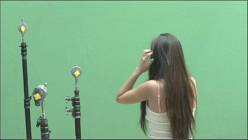
Another way of removing parts of an shot is to use the framehold node, this node takes a frame from the original sequence and freezes on that frame. An issue with this method is that in a video the noise that appears is constantly changing, but in a frozen frame the noise will be static, this can be over come by using a combination of nodes; the Denoise node and the grain node. The images below show the before and after of a shot and the node graph for that shot.


A tracker node is also used to compensate for any camera movement. The way in which the noise is matched is first by using a denoise node on the frozen patch, this completely removes any noise from the image. The grain node is then connected to the denoise node, this allows you to see the grain being applied by the node. Using the rest of the shot as reference, the RGB values of the noise are edited to match the noise in the original image; using the viewer to cycle between the RGB channels.
Complex Cleanup
In a shot with more camera movement in a planar track can be used. This allows for the framehold technique to be used to remove unwanted objects or people from a scene.


The images above show the result of using the framehold technique, combined with the rotopaint technique and a planar track. The node graph can be seen below.

A roto shape is used to get a planar track from the sequence, this data is then applied to a 'CornerPin2D' node so that it can be used by the patch created by a combination of a rotopaint and framehold node. A roto shape is then used to cutout the patch (Below), this then has a grade applied to better match the surrounding environment, a roto shape is used to create a feathered edge to the grade to better blend it with the original plate. All of this is then merged back on top of the original plate.


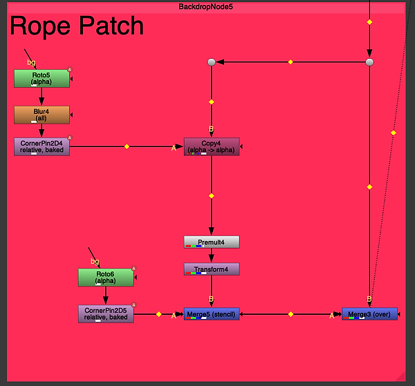
A similar technique can be applied to the above shot. A Planar track is created using the small dock area, as using the water would result in a bad track as it has motion of its own. This data can then be applied to roto shapes that copy parts of the water, these patches of water can then be moved on top of parts that you want to remove, for example, the rope connected to the closest boat, and even the boat itself.


Advanced Cleanup
In this exercise we had to remove a logo from a cardboard box, however in this clip the logo is occluded by an arm and then by a shadow. Using a patch to cover the logo requires the rebuilding of the shadow and the rotoscoping of the arm. A before and after image is shown below.
![PatchRemoval_v01_003.nk [modified] - Nuk](https://static.wixstatic.com/media/15f6aa_d7e87632de4f4fac9852976e9a183854~mv2.png/v1/fill/w_930,h_489,al_c,q_90,usm_0.66_1.00_0.01,enc_avif,quality_auto/PatchRemoval_v01_003_nk%20%5Bmodified%5D%20-%20Nuk.png)
![PatchRemoval_v01_003.nk [modified] - Nuk](https://static.wixstatic.com/media/15f6aa_982fb2452a444eaf9d651ea0fd770b3c~mv2.png/v1/fill/w_930,h_489,al_c,q_90,usm_0.66_1.00_0.01,enc_avif,quality_auto/PatchRemoval_v01_003_nk%20%5Bmodified%5D%20-%20Nuk.png)
Below is the node graph of this exercise. You can see how it is split into the three major parts of the composition, the patch that covers the logo, the rebuilt shadow and the rotoscoping of the arm that occludes the patch.
![PatchRemoval_v01_003.nk [modified] - Nuk](https://static.wixstatic.com/media/15f6aa_d30964a49a444051a296a539fbfc7d53~mv2.png/v1/crop/x_479,y_80,w_936,h_928/fill/w_530,h_524,al_c,q_85,usm_0.66_1.00_0.01,enc_avif,quality_auto/PatchRemoval_v01_003_nk%20%5Bmodified%5D%20-%20Nuk.png)
Below is a screen recording of the workflow for this script.
The first step is to planar track the logo on the box, this will later allow for the cleanup patch to be tracked onto the box. The next step is to create the cleanup patch, this is done by creating a framehold node and then using the clone brush of the 'rotopaint' node to paint over the logo. To finalise the patch a roto shape is created around the logo, this defines the dimensions of the patch. After this the patch is then merged on top of the original image, the 'cornerpin' node created by the planar track is then placed before the 'merge' node, this ensures that the patch follows the box. Next a series of grade nodes are applied to the patch, these nodes then manipulate the luminance values of various parts of the patch to better match it to the scene, these values are animated to ensure the patch matches the scene throughout the changing light conditions. After the patch has been matched the shadow that occludes it has to be rebuilt. This is done by creating a grade node that has an animated rotoshape acting as a mask, the rotoshape is animated to follow the shape of the original shadow. This grade node has to be placed after the cornerpin node as it has an animation of its own and does not need to be tracked onto the box. The final step is to roto the arm that occludes the patch at the beginning of the clip. This is done in a similar way to the shadow, but only uses a roto node that is then merged using the Stencil mode.
Core Skills Recap
The first exercise that we completed was to replace a logo on a box with another new logo. Below is a before and after.
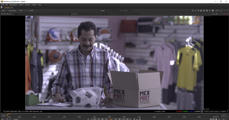

To do this a couple of patches had to be created to cover the original logo, this is done the same way as the advanced cleanup method. The replacement logos then have to be added to the comp, this is done by using a series of transform nodes, a cornerpin node is used to simulate the depth of the box so that the logo looks like it belongs in the scene.

Below is a screen recording of creating the script.
The second exercise was to cleanup and key a green screen sequence.


Below is the node graph for the script, you can see how the script is split into four pieces, the key, cleanup, extra cleanup and merging and grading.

Below is a screen recording of creating the script.
In Class Task
The above video is the final result of the In Class task, the screenshots and explanations below will show a breakdown of the techniques used in this clip.


The two screenshots above show a before and after of the clip we were assigned. We had to remove the logo on the bag, add a colour bar image to the TV, remove the tracking markers and change the colour of the green-screen background. Below is the node graph of these techniques.
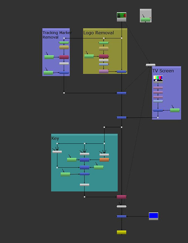
I used backdrop nodes to split the graph into the various parts of the composition. The first part I tackled was the removal of the logo on the bag. Below is a closer look at that part of the node graph.

Removing the logo has a fairly simple workflow, to start the RotoPaint node is used to paint over the logo. A Framehold node is then used, this takes the frame that was painted on and only displays that frame throughout the entire clip. An roto node is then used to draw around the patch, when a Premult is applied this cuts out the patch, this allows it to be added on top of the original clip. A CornerPin2D node is then used, this node uses data gathered by a Planar track to track the patch onto the bag throughout the whole clip. This is then combined with the original plate using a Merge node. Below is an image of the removed logo.

The next stage I tackled was the removal of the tracking markers that appear on the wall. This uses the same workflow as the logo removal, utilising a RotoPaint patch. However as the person in the clip walks in front of the tracking markers I also had to create a roto around him. This can be seen after the Premult node, the roto is merged using the stencil operation as oppose to the over operation. This is then added to the composition using another merge node (with the over operation). Below is an image showing the removed markers.

I then moved onto the TV Screen, this is a completely different workflow to the two previous parts. A colour bars image is imported, this is then passed through a Reformat node, this ensures that the image matches the dimensions of the original plate. A CornerPin node is then used, this allowed me to line the corners of the image up with the corners of the TV, giving the illusion that it was actually being displayed, the transform node also plays a part in this process. A grade node is then added, this allows for the colour of the image to be matched to the colour of the original footage. The roto that I had created for the person was also used in this part, it is added using a Merge node set to stencil. This allows for the person to walk in front of the television and not be occluded by the image. Below is an image of this.


The final stage was to change the colour of the background. This was done by combing various Keylight nodes using the Keymix node. This allows for multiple shades of green to be sampled and combined into one matte. The Keymix node uses a mask created by a Roto node to define the area you want mixed. The Roto7 node is made up of several different roto shapes that cleanup any parts that were missed by the Keys before it. Below is an example of the Alpha created by this process. The alpha produced is added to the comp using a copy node, the colour is then changed by merging a constant over the original plate.
